Creating models using GrxUI
In this section we describe how to create VRML models for OpenHRP using GrxUI. Required dataPlease be prepared with following data.
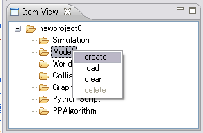
Let's begin model makingRight-click on "Model" item displaying on in GrxUI's ItemView panel and select "create".
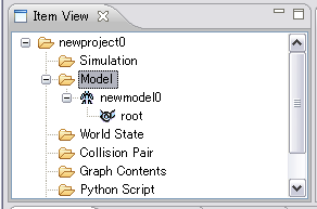
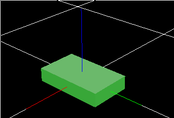
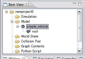
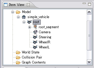
Robot(note the robot icon) and its root link is generated as shown below.
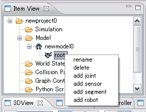
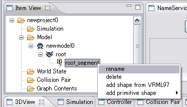
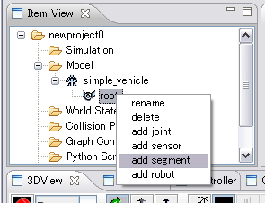
Generating treeRight-clicking link item opens a menu as shown below. Select "add joint", "add sensor", "add segment", to add child link, sensor or segment to this link. Moreover, the already created model file can be read by choosing "add robot".
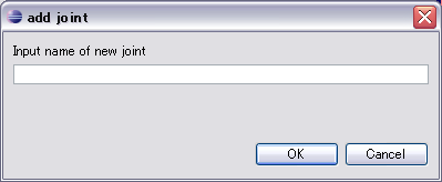
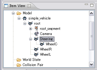
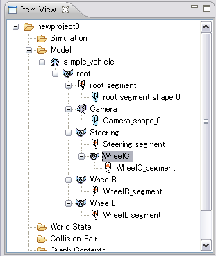
Robot's link tree will be generated by adding necessary items through these menus. Adding child linkRight-click on link item and select "add joint" from menu. Enter the child link name in the poping up dialog box and press OK.
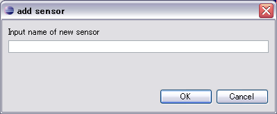
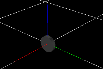
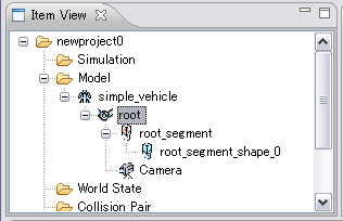
Adding sensorRight-click on link item and select "add sensor" from menu. Enter the sensor name in the poping up dialog box and press OK.
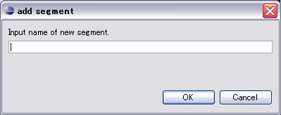
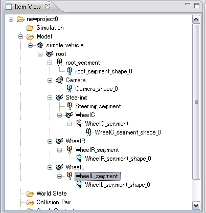
Adding segmentRight-click on link item and select "add segment" from menu. Enter the segment name in the poping up dialog box and press OK.
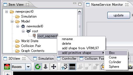
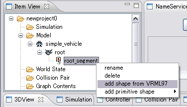
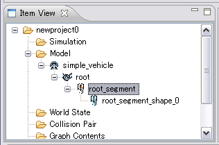
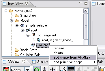
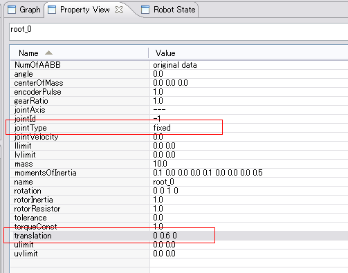
Adding robotRight-click on link item and select "add robot" from menu. Please choose a file in a file dialog. The file must be defined according to the model description of OpenHRP3. The route link of the read file is added as a child link of the selected link. If jointType of the route link of the read file is "free", a simulation cannot be performed correctly. Please be sure to rewrite in another types, such as "fixed", by setup of the property explained below. Adding shapeRight-click on segment item or sensor item and select "add shape from VRML97", "add primitive shape" from menu, to add shape.
Adding shape by VRML97 fileIf you select "add shape from VRML97", file-select dialog box will be opened. Select the previously prepared VRML97 file that contain shape data and press OK. Adding primitive shapeIf you select "add primitive shape", Furthermore, the menu of Box", "Cone", "Cylinder", and "Sphere" is showed. Please choose either.
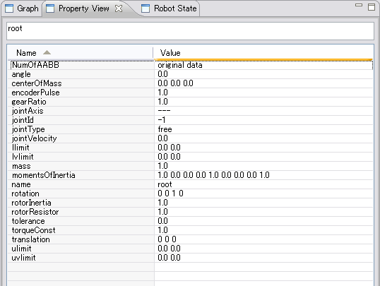
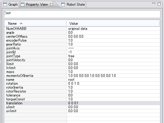
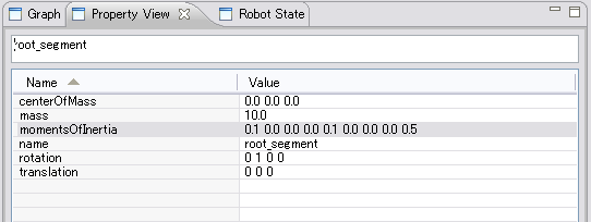
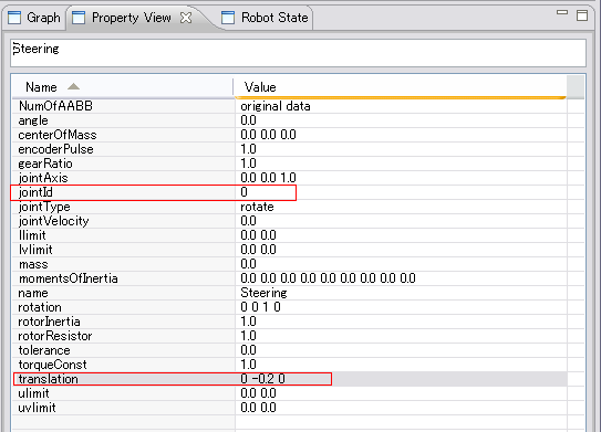
Configuring item propertiesWhen you select link or sensor item, its properties are displayed in "PropertyView" panel. There you can edit the properties and input the predefined parameters of the robot. All the property values are in SI units. Link propertiesEach link contains following properties.
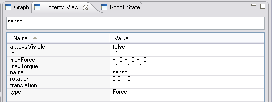
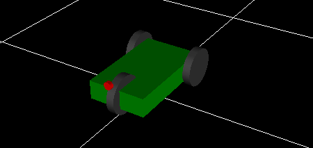
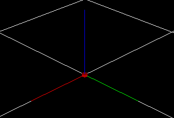
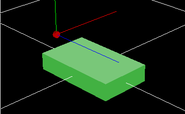
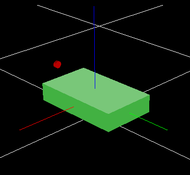
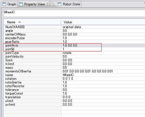
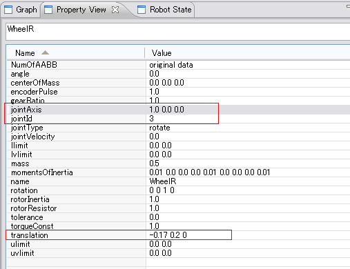
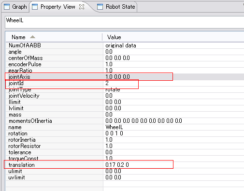
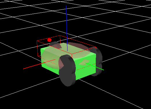
"translation" and "rotation" are for position and orientation of this link relative to the parent link. For "translation", set the position of this link with x,y,z coordinates relative to the parent link's coordinate system and for "rotation", set the orientation of this link by defining rotation vector with 3 elements relative to the parent link and the rotation angle, as total of 4 elements. These position and orientation parameters are same to the sensor and shape items. Numbers below the decimal point are omitted for some properties such as "translation", to prevent the view being complicated. "centerOfMass", "inertia" and "mass" each indicates barycenter position, inertial matrix around the barycenter, and mass of this link. When the link item is selected in ItemView, the ellipsoids that correspond to these mass characteristics are displayed in translucent orange. These values cannot be edited. These can be edited in the property of a segment item. "encoderPulse", "rotorResistor" and "torqueConst" each indicates pulse count, rotor resistance and torque constant that the encoder outputs when the motor makes one rotation. These properties are used by controller, but not in simulation. "gearRatio" and "rotorInertia" each indicates gear ratio of the joint which this link and parent link are connected and the inertia of the motor. These parameters have to be set appropriately, if joint is controlling torque, or simultaion would be unstable. "jointAxis", "jointId" and "jointType" each indicates direction of joint-axis, joint-number and type of the joint. Direction of joint-axis is specified relative to this link's coordinate system. Joint number is the index of this link, when all the joint data is arranged on a vector. Therefore, the number should not be duplicate. JointType can be selected from free-joint(free), rotate-joint(rotate), slide-joint(slide) or fixed-joint(fixed). "llimit", "ulimit", "lvlimit", "uvlimit" each indicates minimum value of movable range, maximum value of movable range, minimum value of speed and the maximum value of speed of this link. These are also for controller to use, but not in simulation. Sensor properties
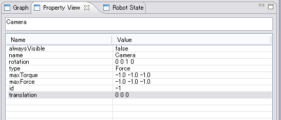
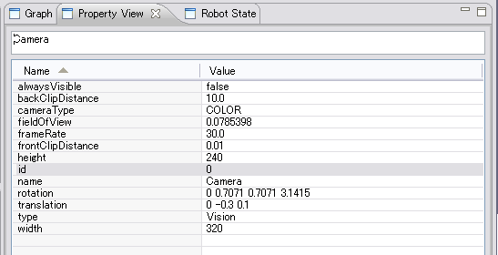
Each sensor has following properties. "type" means type of the sensor that can be selected from acceleration-sensor(Acceleration), angular-velocity-sensor(Gyro), force/torque-sensor(Force) or camera(Vision). Specify the position and orientation for "translation" and "rotation" relative to the link which this sensor is attached.
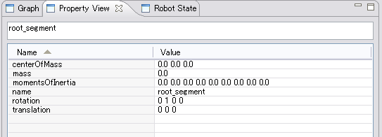
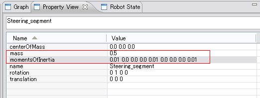
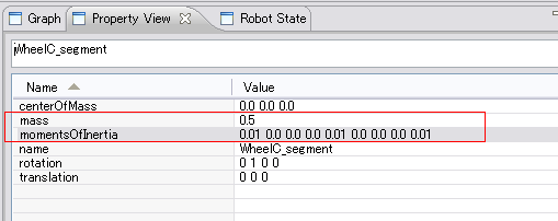
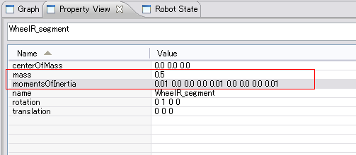
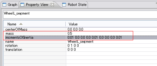
Segment propertiesEach segment has following properties. "centerOfMass", "inertia" and "mass" each indicates barycenter position, inertial matrix around the barycenter, and mass of this segment. Specify the position and orientation for "translation" and "rotation" relative to the link which this segment belongs.
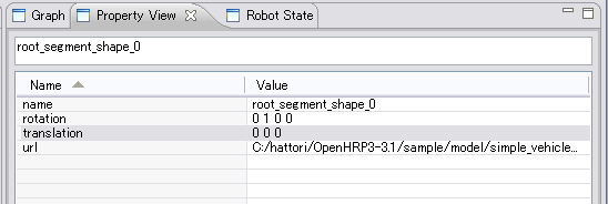
Shape properties
Each shape has following properties.
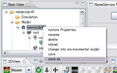
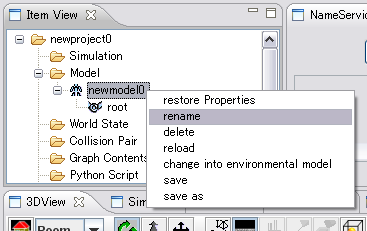
Saving the modelRight-click the robot-item at the top of the item tree; a menu will be popped-up as shown below. Select "save as"; file saving dialog box will be displayed. Provide the model file saving location and file name; then press OK. The created model file will be saved in VRML97 format which is supported in OpenHRP.
Warning
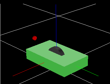
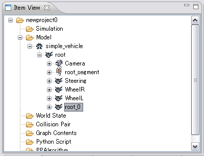
Model making tutorialIn this section we explain step-by-step procedure of how to create the cart model placed in "sample/model/simple_vehicle" directory.
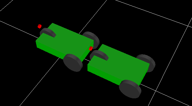
Combination of a modelSince one set of cart model was created, let's create the robot which connected one more set of the same cart model.
|