
OverviewWith OpenHRP version 20001215, we could distribute a walk-pattern attached simple humanoid robot model, thanks to the cooperation of Prof.Takanishi from Waseda University. Here we are going to explain the contents of a Sample Humanoid Robot. Sample Humanoid RobotThe Sample Model (File: $OPENHRPHOME/etc/sample.wrl) is composed of 1 waist-joint (WAIST), 4 body-joints(WAIST_JOINT0 - CHEST), 2 head-joints (HEAD_JOINT0, HEAD_JOINT1), 16 arm-joints(LARM_SHOULDER_P - LARM_WRIST_R, RARM_SHOULDER_P - RARM_WRIST_R), and 14 foot-joints(LLEG_HIP_R - LLEG_ANKLE_R, RLEG_HIP_R - RLEG_ANKLE_R). It would be easy to figure out by referring the Joint-Segment layered structure shown below. Please refer Fig.2 and Fig.3, for more details about joint position, the coordinate-system of each joint, and the segment name corresponding with each link.
(Joint  Joint Node Name  : Segment  Segment Node Name)
Humanoid SAMPLE
|
| # Root
+-humanoidBody
  |
  | # Upper half body
  +-Joint WAIST : Segment WAIST_LINK0
  |   Joint WAIST_P : Segment WAIST_LINK1
  |     Joint WAIST_R : Segment WAIST_LINK2
  |       Joint CHEST : Segment WAIST_LINK3
  |       |
  |       | # Cameras
  |       +-VisionSensor VISION_SENSOR1
  |       +-VisionSensor VISION_SENSOR2
  |       |
  |       | # Left arm
  |       +-Joint LARM_SHOULDER_P : Segment LARM_LINK1
  |       |   Joint LARM_SHOULDER_R : Segment LARM_LINK2
  |       |     Joint LARM_SHOULDER_Y : Segment LARM_LINK3
  |       |       Joint LARM_ELBOW : Segment LARM_LINK4
  |       |         Joint LARM_WRIST_Y : Segment LARM_LINK5
  |       |           Joint LARM_WRIST_P : Segment LARM_LINK6
  |       |             Joint LARM_WRIST_R : Segment LARM_LINK7
  |       |
  |       | # Right arm
  |       +-Joint RARM_SHOULDER_P : Segment RARM_LINK1
  |           Joint RARM_SHOULDER_R : Segment RARM_LINK2
  |             Joint RARM_SHOULDER_Y : Segment RARM_LINK3
  |               Joint RARM_ELBOW : Segment RARM_LINK4
  |                 Joint RARM_WRIST_Y : Segment RARM_LINK5
  |                   Joint RARM_WRIST_P : Segment RARM_LINK6
  |                     Joint RARM_WRIST_R : Segment RARM_LINK7
  |
  | # Left Leg
  +-Joint LLEG_HIP_R : Segment LLEG_LINK1
  |   Joint LLEG_HIP_P : Segment LLEG_LINK2
  |     Joint LLEG_HIP_Y : Segment LLEG_LINK3
  |       Joint LLEG_KNEE : Segment LLEG_LINK4
  |         Joint LLEG_ANKLE_P : Segment LLEG_LINK5
  |           Joint LLEG_ANKLE_R : Segment LLEG_LINK6
  |
  | # Right Leg
  +-Joint RLEG_HIP_R : Segment RLEG_LINK1
        Joint RLEG_HIP_P : Segment RLEG_LINK2
          Joint RLEG_HIP_Y : Segment RLEG_LINK3
            Joint RLEG_KNEE : Segment RLEG_LINK4
              Joint RLEG_ANKLE_P : Segment RLEG_LINK5
                Joint RLEG_ANKLE_R : Segment RLEG_LINK6
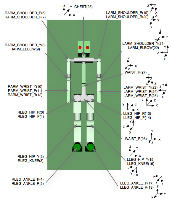 Fig 2. Position and coordinate-system of each Joint on robot 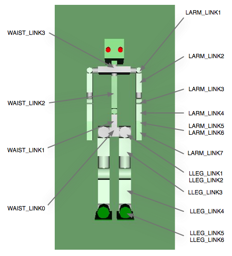 Fig 3. Segment name corresponding to each Link on robot VisionSensorAs described above, there are two Vision Sensors attached under the CHEST. CHEST +-VisionSensor VISION_SENSOR1 +-VisionSensor VISION_SENSOR2 The coordinate system of the Vision Sensors is shown below in Fig 6. The red line is represents X-axis, likewise green line for Y-axis and blue line for Z-axis. The Vision vector(the direction where the camera is facing at) is the opposite direction of Z-axis (0, 0, -1). Please refer the file "sample.wrl", for concrete numerical values of positional posture.  Fig 6. Coordinate-system of the Vision Sensors |