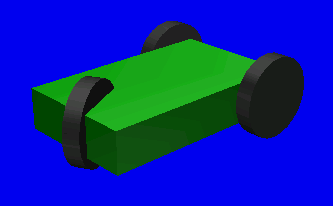
OverviewIn this page, we demonstrate a sample robot model of a cart which is cooperated with RTC, that has a wheeled mechanism and can be operated interactively by using joystick. Both Controller and the joystick of this sample are made as OpenRTM components, and they are connected visually by using OpenRTM tools. The model we concern in this article is the following cart model(Fig.1), that is one of the sample models available in OpenHRP.
It has 3 wheels and can be steered by front wheel (the side having one wheel). The model consists of 4 rotational joints in total; one for steering and three for wheels(1 per each wheel). The model file of this sample can be located at "etc/simple_vehicle.wrl" in OpenHRP3 source. Moreover the set of project files and sample programs described below are available at "sample/JoystickControl" in OpenHRP3 source directory. PreparationSince this sample requires OpenRTM based environment, the following packages/tools are need to be configured on your system.
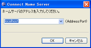
Please refer OpenRTM-aist manuals, for the installation procedure of these software. You may note that source and pre-built packages are available to download. However you better select pre-built packages if you are not upto developing purpose. Starting NameserverIn CORBA and OpenRTM, the program called "Nameserver" is usually used to refer the objects generated at various places in system. For this, it is necessary to start the name server beforehand. Nameserver can be started by any of the following methods.
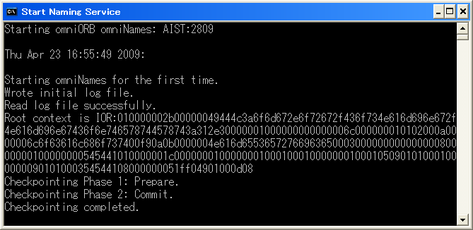
When nameserver is started using GrxUI, GrxUI restart/termination effects on OpenRTM and its components' operation. Therefore it is better if you can keep the nameserver started beforehand. The start-up commands for Ubuntu and Windows are described below. On UbuntuIn Ubuntu, nameserver starts automatically if OmniORB is installed as a package; let's confirm this. Run following command on Terminal. $ ps ax | grep omniNames In the output list, check whether "omniNames" is available as a process. If it is available, nameserver is running; and if not, start the nameserver manually as follows. $ sudo /etc/init.d/omniorb4-nameserver start Here we showed using Ubuntu deamon commands, but you can use omniNames commands too. On WindowsWhen OpenRTM-aist is installed using its installer, a short-cut to start nameserver called "Start Naming Service" will be appeared under "Start menu" → "OpenRTM-aist" → "C++" → "examples". When starting nameserver using this short-cut, a console panel window will be displayed as shown below.
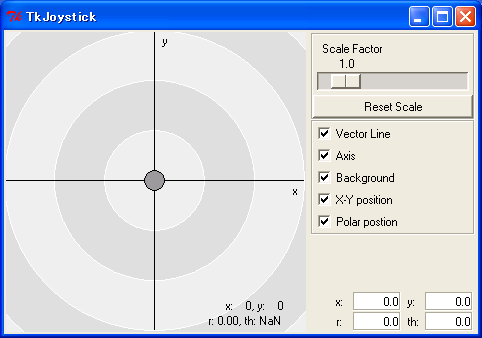
Note: set OMNIORB_USEHOSTNAME=localhost comment out the line to disable the command as follows; rem set OMNIORB_USEHOSTNAME=localhost In this way, the problem will be resolved for the time being. Launch of a joystick componentPlease launch TkJoystickComp.py in sample/JoystickControl/JoysticRTC below the directory which you have extracted OpenHRP3. It will display the screen like the next figure.
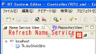
Here, you can drag and move the center circle by your mouse. The location of this circle corresponds with a gradient of the joystick. This program is made as a component of OpenRTM, it provides an OpenRTM port which outputs a gradient of the joystick. This port can be connected to an input for another RT component. This time, we connect it to the controller of the robot, and make it possible to operate the robot by this joystick. Launch of RTSystemEditorPlease start Eclipse in which RTSystemEditor has been installed. Once Eclipse started, open RTSystemEditor perspective. In "NameServiceView", press "Refresh Name Service" button, and you will see an item "JoyStick0|rtc", which corresponds with the joystick component you launched earlier on.
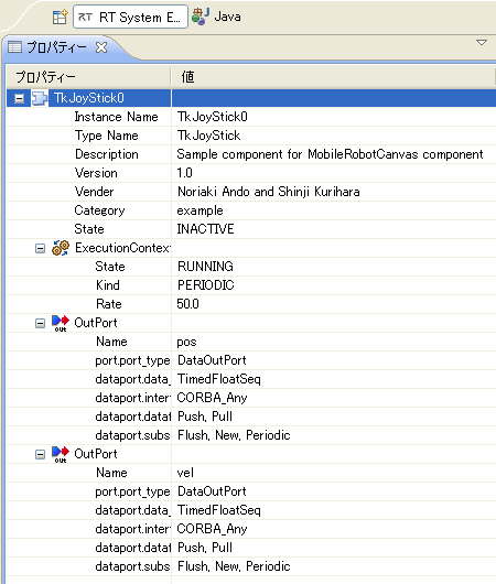
Click an item JoyStick0|rtc, properties of this component will be shown in the Property Window.
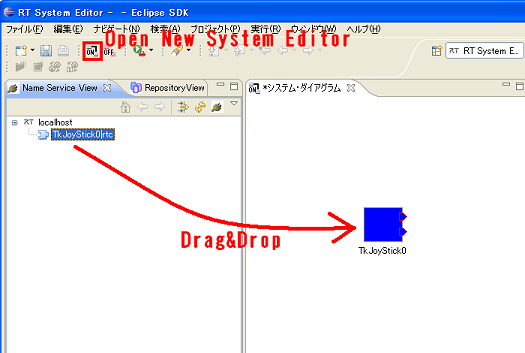
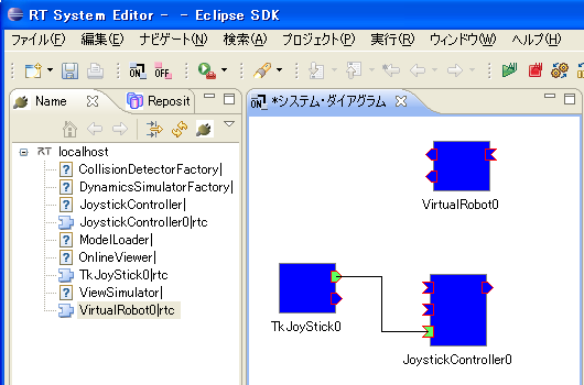
Next, click the item "Open New System Editor" from File menu or the tool button on Eclipse, and make SystemDiagram window visible. From NameServiceView, drag the item Joystick0 to SystemDiagram. The component of Joystick will be displayed on SystemDiagram window.
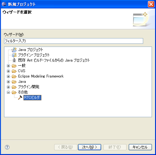
Generating the Skeleton using RTCBuildernew project
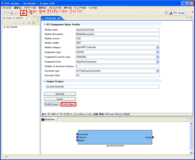
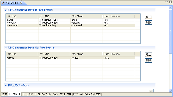
Start RTC Builder. Module setupClick a "Open New RtcBuilder Editor" button or file menu "Open New RtcBuilder Editor", and display the window of RTCBuilder. �B A setup of the controller is saved at sample/JoystickControl/JoystickController.xml. Click a "Profile Import" button and select JoystickController.xml in a file open dialog. Open a basic profile input page. "Module name" is set to "JoystickController". Port setupOpen a data port page. Please see "RT-Component Data InPort Profile". A port called angle, velocity, and command is defined. Angle and velocity are the ports into which a robot's joint angle outputted from a simulator and joint angular velocity are inputted. Command is the ports into which x,y position outputted from a joy stick component is inputted. The torque for controlling a robot is calculated from this input value. A port called torque is defined as "RT-Component Data OutPort Profile". It is a port which outputs the joint torque value which controls a robot.
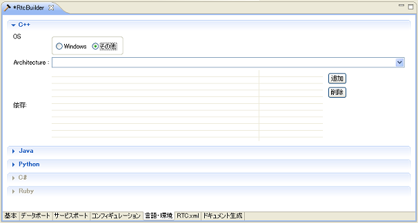
Builder Language setupOpen a language and environment page. A programming language and compile environment are specified.
Generating the SkeletonReturn to a basic profile input page, and push code generation button to generate the skeleton of the component. The directory of a project name is generated in the work space directory of eclipse. Coding of contoller componentBy operations in the previous section, RTCBuilder generates a template code for a component, but of course, component developers have to write the part of its actual movement (which we call its core logic). In RT-Component, several functions for actions of a component are defined on ahead. Its developers can override some of them in accordance with a kind of an action, and make a controller they need. In this example, we will implement those functions on "JoystickController.cpp" which were generated as a template. You can read OpenRTM manual to see details about overridable functions defined in OpenRTM. This time, we will override "onInitialize" method which initialize during creation of components, and "onExecute" method which is called periodically for control and so on. Override of onInitialize methodIn "JoystickController.cpp", original onInitialize function is commented out. Enable the commented code and describe as below.
RTC::ReturnCode_t JoystickController::onInitialize()
{
  // initialize port
  m_torque.data.length(4);

  return RTC::RTC_OK;
}
Here, we set 4 to size of the double array which is used for torque output port in accordance with the number of joints in the robot. As for input ports, since their size are determined by outputs, we don't initialize them explicitly. In addition, uncomment the corresponding function in the header file "JoystickController.h" as well as change to the cpp file. Override of onExecute methodonExecute function which describe control code is a little complicated but we do implement as below. Uncomment the corresponding part of the header file for this function again.
RTC::ReturnCode_t JoystickController::onExecute(RTC::UniqueId ec_id)
{
  // data input from the robot
  m_angleIn.read();
  m_velocityIn.read();
  double steerAngle = m_angle.data[0];
  double steerVel = m_velocity.data[0];
  double tireVel = m_velocity.data[1];

  // data input from the joystick(user)
  m_commandIn.read();
  double steerCommandAngle = 3.14159 * -0.5 * m_command.data[0] / 180.0;
  double tireCommandVel = m_command.data[1] / 10;

  // steering torque calculation
  double steerCommandTorque = 20.0 * (steerCommandAngle - steerAngle) - 2.0 * steerVel;

  // driven torque calculation
  double tireCommandTorque = 1.0 * (tireCommandVel - tireVel);

  // torque output to the robot
  m_torque.data[0] = steerCommandTorque;
  m_torque.data[1] = tireCommandTorque;
  m_torque.data[2] = tireCommandTorque;
  m_torque.data[3] = tireCommandTorque;
  m_torqueOut.write();

  return RTC::RTC_OK;
}
Here, the first element of the input from the joystick, which is x value, is set as a target angle of steering. And the second element of y value is set as a target value of the driven velocity. Based on these target values, torques of steering and driven tires are determined using an appropriate gains. Those changes have been already applied to source files below sample/JoystickControl/ControllerRTC. Thus, you can get an execution file of the component which is implemented the way we have discussed by loading and compiling the project file JoystickController.sln which is a project file of these source files. Creating rtc.confDescribe the settings to run RT-Components in rtc.conf. We have produced the next file: corba.nameservers: localhost naming.formats: %n.rtc exec_cxt.periodic.type: ExtTrigExecutionContext Currently, for an OpenHRP controller, naming.formats and exec_cxt need to be set up as above. ExtTrigExecutionContext is an execution context for synchronization with simulation time, but it doesn't guarantee a perfect synchronization and sometimes has trouble with its operation. In versions 0.4.2 and later of OpenRTM-aist, such a problem will be fixed by a new execution context. Just for this example, there is no big problem which is caused by the context. Creating bridge.confNext we create bridge.conf file which configures how to connect between a simulator and a controller component. In this sample, the file becomes as below: [ComponentName] JoystickController0.rtc [ArrayMappingIn] angle JOINT_VALUE velocity JOINT_VELOCITY [ArrayMappingOut] torque JOINT_TORQUE [PortNameMapping] angle angle velocity velocity torque torque Details about this setting are explained in Creating OpenHRP Controller Manual. Load of OpenHRP simulation projectOnce we finished a controller above, we will make a simulation project on GrxUI, which arranges models and associates controllers with models. Details how to create a simulation project are explained in the manual of GrxUI. Here, load the project which has been already configured. Please load "SimulationProject.xml" below sample/JoysticControl from GrxUI. And on GrxUI, a wheeled type mechanism will appeared on its floor. Here select Tools - Process Manager from GrxUI, and make sure items of JoystickController are checked, please. If compilation of components are successful previously, when the simulation project is loaded, process of components should start and enable thess items (see the next figure).
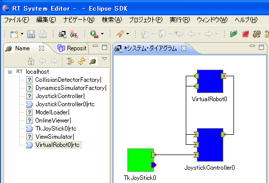
Connecting between a joystick and a controller using RTSystemEditorConnect a controller component to a joystick component.Let's return to RTSystemEditor again. Please drag JoystickController and VirtualRobot from NameServiceView to SystemDiagram as well as a TkJoyStick component. Then connect ports. Drag your mouse from the part of "pos" port on the right upper of TkJoyStick0, to the part of "command" port on the left lower of JoystickController0. These ports are connected each other by a line. Similarly, please also connect the port of angle, velocity, and torque of "JoystickController0", and the port of the same name of "VirtualRobot0." Moreover, select "Active" from the context menu which pops up when you right-click TkJoyStick0, and activate the joystick component. The result we operate as above is the state indicated in the following figure.
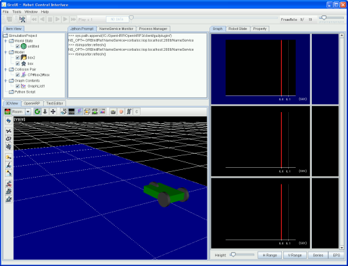
Start of simulation and operation of joystickNow, let's start simulation. Click "Start Simulation" on GrxUI. After this simulation starts, the wheel model may stay stopping. In this state, bring up the joystick window which you have opened on ahead, operate your joystick. The left and right of the joystick correspond with steering, and the top and bottom corresponds with driven power. We hope you can operate your model as if you drive your radio control car. |