Table of contents
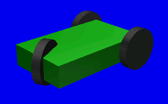
OverviewIn this page, we demonstrate a sample robot model of a cart which is cooperated with RTC, that has a wheeled mechanism and can be operated interactively by using joystick. Both Controller and the joystick of this sample are made as OpenRTM components, and they are connected visually by using OpenRTM tools. The model we concern in this article is the following cart model(Fig.1), that is one of the sample models available in OpenHRP.
It has 3 wheels and can be steered by front wheel (the side having one wheel). The model consists of 4 rotational joints in total; one for steering and three for wheels(1 per each wheel). The model file of this sample can be located at "sample/model/simple_vehicle.wrl" in OpenHRP3 source. Moreover the set of project files and sample programs described below are available at "sample/JoystickControl" in OpenHRP3 source directory. PreparationSince this sample requires OpenRTM based environment, the following packages/tools are need to be configured on your system.
Creation of joy stick plug-inImport
Please choose "Window"->"Opens Perspective"->"Others..." from a menu.
Please choose the "File"->"Import..." from a menu, open a dialog, choose "General"->"Existing Projects into Worlspace", and push a "next" button. CompileA project is built automatically. After an indicator is displayed on the lower right of a status bar and building is completed, it disappears. Export
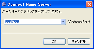
Please choose jp.go.aist.hrp.joystick, choose "File"->"Export..." from a right-click menu, open a dialog, choose "Deployable plug-ins and fragments" of "plug-in development", and push a "next" button. InstallPlease once end Eclipse, copy plug-in of the joy stick to the plugins directory of Eclipse, specify -clean option, and start Eclipse. Starting NameserverIn CORBA and OpenRTM, the program called "Nameserver" is usually used to refer the objects generated at various places in system. For this, it is necessary to start the name server beforehand. Nameserver can be started by any of the following methods.
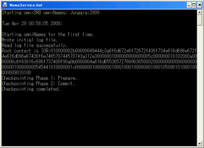
When nameserver is started using GrxUI, GrxUI restart/termination effects on OpenRTM and its components' operation. Therefore it is better if you can keep the nameserver started beforehand. The start-up commands for Ubuntu and Windows are described below. On UbuntuIn Ubuntu, nameserver starts automatically if OmniORB is installed as a package; let's confirm this. Run following command on Terminal. $ ps ax | grep omniNames In the output list, check whether "omniNames" is available as a process. If it is available, nameserver is running; and if not, start the nameserver manually as follows. $ sudo /etc/init.d/omniorb4-nameserver start Here we showed using Ubuntu deamon commands, but you can use omniNames commands too. On WindowsWhen OpenRTM-aist is installed using its installer, a short-cut to start nameserver called "Start Naming Service" will be appeared under "Start menu" → "OpenRTM-aist 1.1" → "C++" → "tools". When starting nameserver using this short-cut, a console panel window will be displayed as shown below.
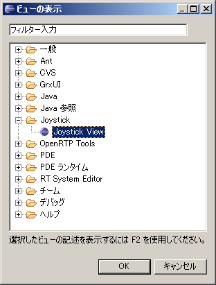
The cautions in name server startingThe name server omniNames of omniORB saves the contents of registration at a log file, and when rebooted, it revives the former contents of registration. Since this structure may start a problem, cautions are required. If a network changes by DHCP etc. and an IP address changes, the system using a name server stops operating well. In order to solve this problem, a former log file is eliminated before name server starting. On Ubuntu $ sudo /etc/init.d/omniorb4-nameserver stop $ sudo rm /var/log/omninames* $ sudo /etc/init.d/omniorb4-nameserver start Starting of a joy stick viewPlease start Eclipse and start GrxUI on Eclipse. Please choose "Window"->"Show View"->"Others..." from a menu, please choose "Joystick"->"Joystick View", and open the Joystick plug-in View.
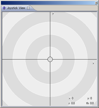
Here, you can drag and move the center circle by your mouse. The location of this circle corresponds with a gradient of the joystick.
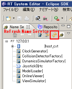
Launch of RTSystemEditorPlease start Eclipse in which RTSystemEditor has been installed. Once Eclipse started, open RTSystemEditor perspective. In "NameServiceView", press "Refresh Name Service" button, and you will see an item "JoyStick0|rtc", which corresponds with the joystick component you launched earlier on.
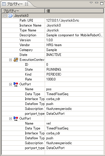
Click an item JoyStick0|rtc, properties of this component will be shown in the Property Window.
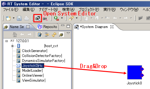
Next, click the item "Open New System Editor" from File menu or the tool button on Eclipse, and make SystemDiagram window visible. From NameServiceView, drag the item Joystick0 to SystemDiagram. The component of Joystick will be displayed on SystemDiagram window.
Generation and starting of a controller componentA component development user needs to describe the portion (it is called core logic) corresponding to actual operation of a component. Here, generation and starting of the controller component of a sample are explained. Compile of a componentBelow "sample/JoystickControl/Controller" has a source file of a sample.Please compile these sauce.
In Windows, please start GUI of CMake, set up required contents, choose the version of VC++, and generate a solution file. In Linux, $ make -f Makefile.JoystickControllerPlease compile to be shown above. in a Controlelr directory. Starting of a controller componentLet's start the component created for the foregoing paragraph and enable it to use in a system. Although there are some methods of starting the component of OpenRTM, in this example, a component is generable by performing the executable file compiled. Correction of rtc.conf
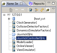
You need to change a "rtc.conf" file which is a configuration file of a component before starting a component. corba.nameservers: localhost naming.formats: %n.rtc exec_cxt.periodic.type: SynchExtTriggerEC Currently, for an OpenHRP controller, naming.formats and exec_cxt need to be set up as above. "exec_cxt" specifies the kind of execution context which determines how the "onExecute" function of a component is made to drive. When connecting the component of a controller with OpenHRP and performing a simulation, a controller needs to be performed synchronizing with progress of the time in the world under simulation. For this reason, you set up an execution context called "SynchExtTriggerEC". In addition, refer to the manual of OpenRTM for the details of the contents of a setting described to rtc.conf. You are able to describe various setting items also besides having set up in the above, and an original setting item. Moreover, how to read rtc.conf also has the method of specifying the file read from a command line. Refer to the manual of OpenRTM also for those details. Starting of a controllerOn WindowsPlease move to this controller directory on a command line, and run JoystickControllerComp.exe.On LinuxPlease move to this controller directory on a command line, and run ./JoystickControllerComp.The check of the component by RTSystemEditorWhen the component of a controller is started, "JoystickController0|rtc" item is added in "Name Service View" of RTSystemEditor as shown in Fig. 9.
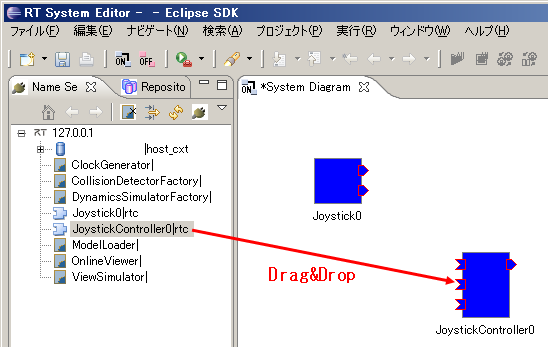
The number is added to the last of the name of a component like JoystickController0 because this is the "instance" of a component. With this sample, "JoystickController" is the "model name" (it is also called "Modulename") of a component. Since two or more "instances" may be generated, in order to distinguish them, in OpenRTM, a number is added to a model name and it is considered as an instance name. Since "JoystickController0" which is this instance name is referred to by setup explained later, please do not forget. Let's drag and display JoystickController as well as a TkJoyStick component on SystemDiagram.
JoystickController0 has four projections and it corresponds to each port which this set up by RTCBuilder. The information of the port is displayed if you place a mouse on a port, please check each port. Port connection of TkJoystick0 and JoystickController0 is made later. Controller bridgeIn OpenHRP3, the program a "controller bridge" connects the model and controller component for a simulation. This program is an executable file called "bin/openhrp-controller-bridge" in OpenHRP3 directory. (In the case of Windows, it is openhrp-controller-bridge.exe. ) A setup of a controller bridgeA command line option can be used for a setup of a controller bridge. With this sample, the shell script file which described the option is created and a controller bridge is started using the file. Please create as follows the file "JoystickController.sh." (This file is in "sample/JoysticControl/Controller". In Windows, it is "JoystickController.bat." ) openhrp-controller-bridge \ --server-name JoystickController \ --out-port angle:JOINT_VALUE \ --out-port velocity:JOINT_VELOCITY \ --in-port torque:JOINT_TORQUE The contents of each option are explained below.
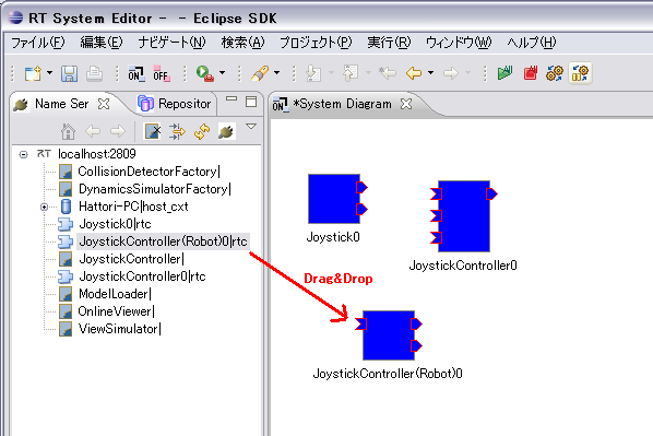
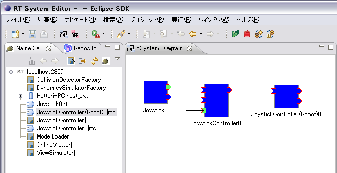
Starting of a controller bridgeLet's start a controller bridge. In the case of Windows, let's double-click and run "JoystickController.bat" on Explorer. When you start from a command line, please start after moving to a Controller directory. Because, RT component which a controller bridge generates also need a setup of rtc.conf, and read a file from a current directory. Controller bridge will generate RT component corresponding to the model for a simulation according to the contents of the option. Let's check this on RTSystemEditor. Please drag "JoystickController(Robot)0" component to "SystemDiagram" from "Name Service View". This component is the component corresponding to the model for a simulation.
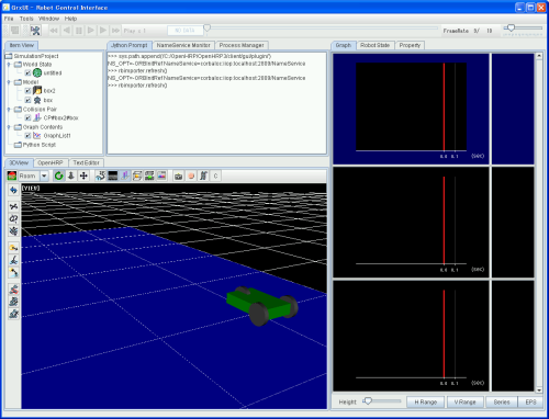
Please check the port of "JoystickController(Robot)0" on RTSystemEditor. It has the port set up as the options "--out-port" and "--in-port" of the controller bridge. The component required for a simulation was prepared. Simulation projectArrangement of a model and matching of a controller to a model are created as a simulation project on GrxUI.�B Let's read the already created project. Refer to the manual of GrxUI for the details about the method of creating a simulation project.Please start GrxUI and read "SimulationProject.xml" in sample/JoysticControl. Then, a wheel type mechanism is displayed on GrxUI.
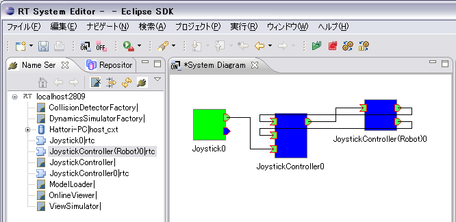
"JoystickController" is specified in "Controller View". This is the name specified as the option "--server-name" of the controller bridge. Since the controller bridge is already started, it is connected with a server at the time of a simulation start. Connection of the joy stick and controller using RTSystemEditorAs the preparation before a simulation, Let's connect a joy stick component and a controller component using RTSystemEditor. On SystemDiagram of RTSystemEditor, three components should already be displayed. Please drag a mouse to the "command" port in the lower left of "JoystickController0" from the "pos" port in the upper right of "TkJoystick0." Please push "OK" in a dialog. Between the ports dragged as shown in Fig. 13 is connected with a line.
This shows that port "pos" and "command" were connected in the OpenRTM system. Now, instructions of a joy stick will be given as a command input to a controller. Similarly, please also connect the port of angle of "JoystickController0", velocity, and torque, and the port of the same name of "JoystickController(Robot)0. Now, connection between three components is completed. However, in order to validate the port output from a joy stick, you have to set a joy stick component to active. Please right-click "Joystick0" and choose "Active" from the menu displayed. Then, the color of a joy stick component changes into green from blue. Preparation of the simulation was completed. Please check RTSystemEditor before a simulation start.
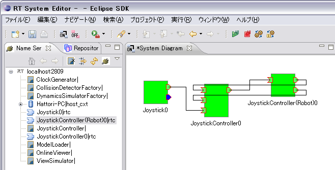
After a simulation start, RTSystemEditor is displayed, as shown in Fig. 15.
The start of a simulation, and joy stick operationLet's start a simulation. Please click the "Start Simulation" button of GrxUI. Please operate a joy stick on a joy stick window. The right and left of a joy stick can respond to a steering, the upper and lower sides correspond to driving force, and it can operate a model like radio control. Development of a controller componentPlease refer a Controller Building Guide (Walking Pattern) about creation of the controller component by RTCBuilder. Coding of a controller componentYou need to describe the portion (it is called core logic) corresponding to actual operation of a component. The function for describing operation is beforehand defined partly by RT component, and a controller can be created by overwriting these functions. The list of the functions which can overwrite is shown below.
Refer to the manual of OpenRTM for the details of the function which can be overwritten. This time, a "onInitialize" method and a "onExecute" method are overwritten. Overwrite of an onInitialize methodIn "JoystickController.cpp", the onInitialize function is commented out in the state of the first stage. Please delete this comment out and describe as follows.
RTC::ReturnCode_t JoystickController::onInitialize()
{
  m_torque.data.length(4);

  return RTC::RTC_OK;
}
The size of the double arrangement of the output port of torque was united with the robot's number of joints, and is set as 4. In an input port, the output side determines size. In addition, please also delete comment out of the corresponding function in header file"JoystickController.h." Overwrite of an onExecute methodPlease describe the onExecute function as follows. Please also change a header file.
RTC::ReturnCode_t JoystickController::onExecute(RTC::UniqueId ec_id)
{
  // Data input from a robot
  m_angleIn.read();
  m_velocityIn.read();
  double steerAngle = m_angle.data[0];
  double steerVel = m_velocity.data[0];
  double tireVel = m_velocity.data[1];

  // Data input from a joy stick (user)
  m_commandIn.read();
  double steerCommandAngle = 3.14159 * -0.5 * m_command.data[0] / 180.0;
  double tireCommandVel = m_command.data[1] / 10;

  // Steering torque calculation
  double steerCommandTorque = 20.0 * (steerCommandAngle - steerAngle) - 2.0 * steerVel;

  // Drive torque calculation
  double tireCommandTorque = 1.0 * (tireCommandVel - tireVel);

  // The torque output to a robot
  m_torque.data[0] = steerCommandTorque;
  m_torque.data[1] = tireCommandTorque;
  m_torque.data[2] = tireCommandTorque;
  m_torque.data[3] = tireCommandTorque;
  m_torqueOut.write();

  return RTC::RTC_OK;
}
x value which is an element of the beginning of the input from a joy stick is set as the target angle of a steering, and y value which is the 2nd element is set up as a desired value of drive speed. The torque of a steering and a driving wheel is determined using a suitable gain so that these desired values may be followed. |