OverviewHere we describe the procedure of building a controller as an OpenRTM component. We take SamplePD as for the example, that makes a robot walk by PD-control based on walking pattern files. The process of making the component is carried out by referring to the sample source codes (SamplePD.h, Sample.cpp) we have provided in OpenHRP source package. Codes that are skipped explaining is referred to the skeleton parts generated by rtc-template. Creating skeleton of a OpenRTM component using rtc-template is described later in "Skeleton Generation" section. Code ExplanationSamplePD.hPlease look at "Controller/rtc/SamplePD/SamplePD.h" . Confirm if "SamplePD::onActivated" and "SamplePD::onExecute" are declared in it. Virtual functions other than "SamplePD::onInitialize", are kept commented out while generating skeletons. By overriding these virtual functions, we can define peculiar behavior to the controller. Various members used by controller, are added. private: int dummy; std::ifstream angle, vel, gain; // Joint-angle, Joint-angular-velocity, gain value double *Pgain; // Array of Pgain double *Dgain; // Array of Dgain std::vector<double> qold; // Preserve previous Joint-angle When building on Windows environment, it is necessary to modify the method "SamplePDInit" to refer the macro "DLL_EXPORT" defined by OpenRTM; so that it will support Windows-DLL builds.
extern "C"
{

  DLL_EXPORT void SamplePDInit(RTC::Manager* manager);

};
SamplePD.cppFirst, we declare header file includes and macro. #include <iostream> #define DOF (29) // Degree of freedom #define TIMESTEP 0.002 // Simulation Time-step (time unit) // File group #define ANGLE_FILE "etc/angle.dat" // Joint-angle #define VEL_FILE "etc/vel.dat" // Joint-angular-velocity #define GAIN_FILE "etc/PDgain.dat" // PDgain value Now, let us implement the methods we declared in "SamplePD.h". After the constructor "SamplePD::SamplePD" is called, the walking pattern file is opened and the PD gain values are taken from the gain file and substitute to the variables.
SamplePD::SamplePD(RTC::Manager* manager)
  : RTC::DataFlowComponentBase(manager),
    // <rtc-template block="initializer">
    m_angleIn("angle", m_angle),
    m_torqueOut("torque", m_torque),

    // </rtc-template>
    dummy(0),
    qold(DOF)
{

...

  Pgain = new double[DOF];
  Dgain = new double[DOF];

  // Opening joint-angle file
  if (access(ANGLE_FILE, 0)){
    std::cerr << ANGLE_FILE << " not found" << std::endl;
  }else{
    angle.open(ANGLE_FILE);
  }

  // Opening joint-angular-velocity file
  if (access(VEL_FILE, 0)){
    std::cerr << VEL_FILE << " not found" << std::endl;
  }else{
    vel.open(VEL_FILE);
  }

  // Opening gain file and substituting to array
  if (access(GAIN_FILE, 0)){
    std::cerr << GAIN_FILE << " not found" << std::endl;
  }else{
    gain.open(GAIN_FILE);
    for (int i=0; i<DOF; i++){
      gain >> Pgain[i];
      gain >> Dgain[i];
    }
    gain.close();
  }

  // Ensuring the length of torque and joint-angle port,
  // to the size of degree-of-freedom(DOF) of the robot
  m_torque.data.length(DOF);
  m_angle.data.length(DOF);
}
"SamplePD::~SamplePD" method is used to freeing arrays and close the file. if (angle.is_open()) angle.close(); if (vel.is_open()) vel.close(); delete [] Pgain; delete [] Dgain; Initializing is done by "RTC::ReturnCode_t SamplePD::onActivated".
RTC::ReturnCode_t SamplePD::onActivated(RTC::UniqueId ec_id)
{
  std::cout << "on Activated" << std::endl;
  angle.seekg(0);
  vel.seekg(0);

  // Updating the joint-angle InPort value
  m_angleIn.update();

  // Preserve the values of previous frame
  for(int i=0; i < DOF; ++i){
    qold[i] = m_angle.data[i];
  }

  return RTC::RTC_OK;
}
"RTC::ReturnCode_t SamplePD::OnExecute" method is used to process the behavior in each step of the simulation.
RTC::ReturnCode_t SamplePD::onExecute(RTC::UniqueId ec_id)
{
  // Updating the joint-angle InPort value
  m_angleIn.update();

  // Updating angle and angular-velocity of each joint
  static double q_ref[DOF], dq_ref[DOF];
  if(!angle.eof()){
    angle >> q_ref[0]; vel >> dq_ref[0];// skip time
    for (int i=0; i<DOF; i++){
      angle >> q_ref[i];
      vel >> dq_ref[i];
    }
  }

  // Calculating torque of the each joint
  for(int i=0; i<DOF; i++){
    double q = m_angle.data[i];
    double dq = (q - qold[i]) / TIMESTEP;
    qold[i] = q;

    m_torque.data[i] = -(q - q_ref[i]) * Pgain[i] - (dq - dq_ref[i]) * Dgain[i];
  }

  // Outputs torque
  m_torqueOut.write();

  return RTC::RTC_OK;
}
FilesIn this section we describe about pattern files and configuration files at "Controller/rtc/SamplePD/". Walking Pattern FilesThese files are related to the "ANGLE_FILE" macro and "VEL_FILE" macro in the code. First let us explain the format of Waking Pattern Files(angle.dat, vel.dat). Format of one line in each pattern file is as follows; Time <Joint-Data where JointID=0> <Joint-Data where JointID=1> .... <Joint-Data where JointID=n> One line corresponds to one frame, and each data in a line are delimited by tab. Time refers to the time-duration elapsed from starting-time. Joint-data refers to joint-angle in "angle.dat" and it refers to joint-angular-velocity in "vel.dat". For instance, 29 joint-data of 6701 frames that executes for 14 seconds has been expressed in the given sample files. Gain File
This file is related to the "GAIN_FILE" macro in the code.
Gain file is used to keep records of PD-control gains. Basically it consists of a collection of
P-gains and D-gains. Each line corresponds to JointID number. An arbitrary number of P-gains and
D-gains (corresponding with JointID) can be written per line, delimiting with spaces. P-Gain D-Gain (<= JointID = 0) P-Gain D-Gain (<= JointID = 1) ... P-Gain D-Gain (<= JointID = n) rtc.conf
Please look at the cofiguration file "rtc.conf" available at "Controller/rtc/SamplePD/rtc.conf". Specify the location(ip address) of the nameserver, according to your environment. corba.nameservers: localhost:2809Specially when "NS_HOST" and "NS_PORT" do not take the default values on your environment, you have to specify the correct values in following files.
OpenHRP.vsprops, bin/dos/config.bat (On Windows) Specify the settings regarding with log files.
logger.enable:YES
Specify the log file's name format and saving location(path). logger.file_name: D:\\Temp\\rtc%p.log Set the log level. logger.log_level: TRACE Normally you don't have to change the following contents. naming.formats: %n.rtc manager.modules.load_path: . exec_cxt.periodic.rate: 1000000 manager.modules.abs_path_allowed: yes exec_cxt.periodic.type: SynchExtTriggerEC Please refer OpenRTM Configuaration manual, for detailed explanation about RT-components' configuration options. Controller-bridge Settings and ExecutionThe purpose of separating the implementation of each RT-component is to improve the maintainability and the portability upon development process. The controller bridge is the process which manage input/outputs(I/O) between the simulating model and each OpenRTM component. Here we describe, how to launch controller-bridge and its connection settings with components. For Linux
Run the shell-script "SamplePD.sh", available at "Controller/rtc/SamplePD/".
#!/bin/sh

CONTROLLER_BRIDGE_DIR=../../bridge
if [ -z $NS_HOST ]; then
    if [ -z $NS_PORT ]; then
        . $CONTROLLER_BRIDGE_DIR/../../bin/unix/config.sh
    fi
fi
$CONTROLLER_BRIDGE_DIR/ControllerBridge \
--config-file bridge.conf \
--name-server $NS_HOST:$NS_PORT
Reference to ControllerBridge may loss, if relative paths to "Controller/bridge" directory and "Controller/SamplePD" directory are changed. You can fix this by changing "CONTROLLER_BRIDGE_DIR" field appropriately. If neither environment variable NS_HOST nor NS_PORT are defined, it acquires them from "bin/unix/config.sh". For WindowsRun the batch file "SamplePD.bat", available at "Controller/rtc/SamplePD/". SET CONTROLLER_BRIDGE_DIR=..\..\bridge @echo off if "%NS_HOST%" == "" ( if "%NS_PORT%" == "" ( call %CONTROLLER_BRIDGE_DIR%\..\..\bin\dos\config.bat ) ) @echo on %CONTROLLER_BRIDGE_DIR%\ControllerBridge ^ --config-file bridge.conf ^ --name-server %NS_HOST%:%NS_PORT% As same as Linux, reference to the ControllerBridge may loss, if relative paths to "Controller/bridge" directory and "Controller/SamplePD" directory are changed. You can fix this problem by changing "CONTROLLER_BRIDGE_DIR" field appropriately. If neither environment variable NS_HOST nor NS_PORT are defined, it acquires them from "bin/unix/config.sh". Moreover, please beware to enclose the path name with double cotations, if it contains spaces. There is something to beware of this batch file execution on windows environments. Unlike Unix environments, omninames server does not register as a service on windows environments at most cases. In such situation, it is necessary to start the omninames server beforehand. To refer the starting procedure of omninames server, visit "Development of RT-Component (VC++)" page at OpenRTM documentations and find the title "Starting CORBA Name Server". Or if you can start GrxUI beforehand and keep it working, omninames server also get started with GrxUI and continue to work. However if you use this method, omninames server will also be exit, with the termination of GrxUI. Start-Options
config-file
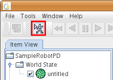
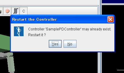
name-server Please refer Controller-Bridge user manual for more details about start options. Loading Project File and Simulation ExecutionLoad the project file to GrxUI and start the simulation process according to the following steps.
Please refer GrxUI User Manual for more about GrxUI. Skeleton GenerationIn this section we describe generating skeleton of a OpenRTM component using rtc-template. Although it is possible to generate the skeleton using command-line, we recommand you to prepare a script file, since there are lot of settings. As you execute this script, it will generate the skeleton of the "SamplePD" component having one Inport named "angle" and one OutPort named "torque". For LinuxPrepare a shell-script as follows; #!/bin/sh rtc-template -bcxx \ --module-name=SamplePD --module-desc="SamplePD component" \ --module-version=0.1 --module-vendor=AIST --module-category=Generic \ --module-comp-type=DataFlowComponent --module-act-type=SPORADIC \ --module-max-inst=1 \ --inport=angle:TimedDoubleSeq \ --outport=torque:TimedDoubleSeq Please refer "Development of RT-Component" page in OpenRTM documentations, for more details on rtc-template (Linux C++ edition). For WindowsPrepare a batch file as follows; "C:\Program Files\OpenRTM-aist\0.4\utils\rtc-template\rtc-template.py" -bcxx ^ --module-name=SamplePD --module-desc="SamplePD component" ^ --module-version=0.1 --module-vendor=AIST --module-category=Generic ^ --module-comp-type=DataFlowComponent --module-act-type=SPORADIC ^ --module-max-inst=1 ^ --inport=angle:TimedDoubleSeq ^ --outport=torque:TimedDoubleSeq Executing this batch file will produce a solution file and a project file for VC++ 2008. After that run "copyprops.bat", generated by rtc-template. For concrete explanation regarding rtc-template (Windows VC++ edition), please refer "Development of RT-Component (VC++)" page in OpenRTM documentations. |