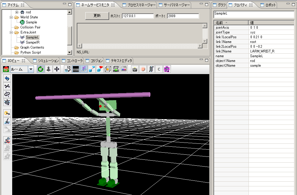
Overview
If a virtual joint is set up between the links of a separate model, constraint force can be generated between the specified links.
The constraint force in alignment with the specified axis is generated noting that two links are connected with ball joint.
When this is used, for example, you can make a robot hang down from the iron bar.

Fig 1: Extra Joint Sample
Here, the procedure of setting up a virtual joint is explained.
Creation of a extra joint
Items are set up like other simulations and a project is created.
Please right-click the ExtraJoint folder of an item view and choose "create" from a menu.
Selection of the created ExtraJoint item will display the contents on a property view. Please edit this.
The meaning of a property is as follows.
| name | Name of the virtual joint |
| link1Name | Name of the link which has received ball joint |
| link2Name | Name of the link to which ball joint is attached |
| object1Name | The model name of link1Name |
| object2Name | The model name of link2Name |
| link1LocalPos | Connection (joint) position in the local coordinate of the link1Name link |
| link2LocalPos | Connection (joint) position in the local coordinate of the link2Name link |
| jointType | The number of constraint axes. xyz:three each other orthogonal axes. xy: two orthogonal axes to the axis specified by jointAxis. z:one axis specified by jointAxis. |
| jointAxis | >A unit vector is specified by the local coordinate of the link1Name link. The meaning of a vector changes by specification of jointType. |
Execution of a sample
Please start GrxUI and load project ExtraJoint.xml.
Please start a simulation.
